

Why Choose a Chemical Injection System?
Industrial facilities rarely fail because of one dramatic event. Small dosing errors can slowly increase corrosion, scaling, fouling, and maintenance costs. A chemical injection system delivers measured treatment chemicals into pipelines, tanks, and process equipment. It can support safer, more consistent control than manual pouring.
The financial reason is substantial. The NACE IMPACT study estimated global corrosion costs at approximately US$2.5 trillion annually, equal to about 3.4% of global GDP. This figure does not mean chemical injection eliminates corrosion. It shows why prevention deserves engineering attention. In oil and gas operations, corrosion inhibitors can protect carbon-steel lines, valves, and separators. In water treatment, antiscalants and biocides can help maintain flow and heat-transfer performance.
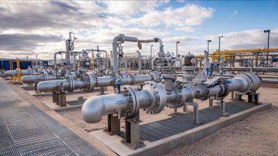
The equipment is practical and visible. Operators can check a calibration cylinder, inspect injection tubing, and compare pump output with process demand. Flow-paced control may adjust dosing when production changes. Remote monitoring can also reveal an empty tank or blocked quill before damage spreads. These details matter during long shifts and harsh weather.
Still, the choice is not automatic. Poor chemical selection, inaccurate calibration, or weak maintenance can create new risks. The U.S. Environmental Protection Agency emphasizes process control, monitoring, and preventive management in water systems. Those principles apply here. A reliable chemical injection system should match fluid chemistry, pressure, temperature, and operating conditions. Site testing remains essential. No brochure can replace it.
What Is a Chemical Injection System? Core Equipment and Functions
Why Choose a Chemical Injection System?
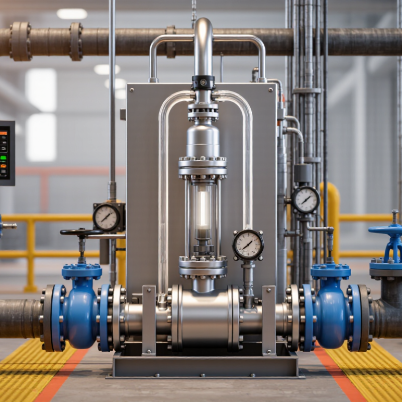
A chemical injection system delivers measured chemical volumes into a process line, vessel, or treatment point. It supports stable dosing when manual pouring becomes inconsistent or unsafe.
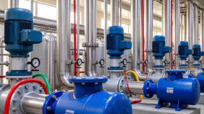
A typical system includes a storage tank, metering pump, calibration column, pressure gauge, check valve, and injection quill. The tank holds the prepared solution. The pump controls flow rate and pressure. The calibration column helps operators verify actual output before operation. Check valves reduce backflow risk, while the injection quill distributes chemical into the process stream.
Some systems also include mixers, pulsation dampeners, relief valves, and automated flow controls.
In water treatment, dosing may support pH adjustment, disinfection, or scale control. In industrial processes, it can manage corrosion and production consistency.
Accurate dosing matters. Small errors matter.
Field experience shows that equipment selection must match viscosity, temperature, pressure, and chemical compatibility. A pump that handles water may struggle with a thicker solution. Seals can swell, crack, or leak when materials are poorly matched.
Operators should inspect tubing, connections, and calibration readings during routine rounds. The control panel may improve monitoring, but automation does not replace practical checks. Manual adjustment remains useful during commissioning and unusual process conditions.
A clean design can still fail when the suction line is too long or poorly supported. That detail is easy to overlook. Safety procedures, ventilation, containment, and accessible isolation valves should be built into the installation rather than added later.
Corrosion Control: NACE Estimates $2.5 Trillion in Annual Losses
Why Choose a Chemical Injection System?
Corrosion is not merely a maintenance issue. It can weaken pipelines, vessels, valves, and supports long before failure becomes visible.
The NACE IMPACT study estimated global corrosion costs at about $2.5 trillion annually, equal to roughly 3.4% of global gross domestic product.
That figure is significant, but it is not a universal invoice. Costs vary by asset age, operating conditions, inspection quality, and local repair practices.
A chemical injection system helps deliver corrosion inhibitors at a controlled rate. In field operations, dosing must respond to pressure, temperature, water cut, flow changes, and chemical concentration.
A fixed setting may work during one production phase and fail during another. Small leaks matter. Poor calibration can waste treatment chemicals while leaving metal surfaces exposed.
Reliable protection requires more than installing a pump.
Operators should combine injection-rate verification, sampling, corrosion monitoring, and documented maintenance. The NACE IMPACT study also emphasized prevention as a more economical strategy than repairing corrosion damage after it occurs.
International standards, including ISO 17359 for condition monitoring, support structured inspection programs, although they do not replace engineering judgment.
A chemical injection system is therefore one part of a wider integrity plan. Its value depends on correct chemical selection, accurate metering, and evidence that the treatment is working.
Even experienced teams must question old assumptions when process conditions change.
Dosing Precision: How API 675 Shapes Metering-Pump Selection
Why Choose a Chemical Injection System?
Dosing Precision: How API 675 Shapes Metering-Pump Selection
A chemical injection system protects process stability when small volume errors create costly consequences. API 675 focuses on controlled-volume metering pumps and their repeatable performance. It guides engineers toward measured flow, dependable adjustment, and documented testing.
Start with the real duty point, not the catalog headline. Record flow rate, discharge pressure, fluid temperature, viscosity, and chemical compatibility. A pump may meet its rated capacity but struggle at low-flow operation. API 675 encourages attention to accuracy, repeatability, capacity control, and mechanical integrity. These details matter near a reactor inlet or a narrow treatment line.
Small errors accumulate.
Field reviews often reveal a practical weakness: calibration is treated as a final task. It should support selection from the beginning. Check whether the pump can maintain stable dosing across the expected turndown range. Confirm relief protection, pulsation control, diaphragm materials, and accessible inspection points. A clear test record improves confidence, but it cannot replace site-specific judgment. I would also question overly precise promises when fluid properties change during operation. The standard provides a strong engineering framework, yet installation quality, calibration habits, and operator training still shape daily reliability.
Why Choose a Chemical Injection System? - Dosing Precision: How API 675 Shapes Metering-Pump Selection
| Selection Dimension | API 675-Oriented Reference | Indicative Design Data | Why It Matters for Chemical Injection |
|---|---|---|---|
| Metering principle | Controlled-volume positive-displacement pump | Fixed displacement per stroke; flow adjusted by stroke length, speed, or both | Provides predictable chemical delivery even when discharge pressure changes. |
| Capacity accuracy target | API 675 applications commonly specify approximately ±1% capacity accuracy under defined operating conditions | Design target: within ±1% of the required metering rate after calibration | Helps maintain the intended inhibitor, biocide, corrosion-control, or treatment concentration. |
| Repeatability | Repeatability is evaluated separately from absolute accuracy and depends on pump, liquid, and installation conditions | Typical project specification: approximately ±3% repeatability or better | Supports stable dosing during repeated operating cycles and automatic control. |
| Flow turndown | A 10:1 turndown range is commonly used for API 675 metering-pump selection and testing | Example operating range: 10 to 100 L/h | Allows one pump to accommodate changing production rates and seasonal treatment demand. |
| Maximum flow rate | Selected from required injection rate, turndown, liquid properties, and available differential pressure | Example selection basis: 100 L/h maximum; normal operation at 40–80 L/h | Avoids operating continuously at the extreme end of the adjustment range. |
| Discharge pressure | Pump rating must exceed the maximum system pressure, including static head and line losses | Example design pressure: 100 barg, subject to project requirements | Ensures the pump can overcome back pressure without loss of metering control. |
| Pressure differential | Positive-displacement metering pumps require sufficient differential pressure for reliable check-valve operation | A practical installation often maintains at least 1–2 bar differential, subject to pump design | Reduces the risk of reverse flow, siphoning, and inconsistent injection. |
| Stroke frequency | Must be selected with regard to flow rate, liquid viscosity, acceleration, and pulsation requirements | Typical controlled-volume designs operate from low single-digit to several hundred strokes per minute | Lower speed can improve handling of viscous or shear-sensitive chemicals and reduce pulsation. |
| Liquid viscosity | Viscosity must be checked against suction capability, valve response, and calibration conditions | Water-like liquids are commonly near 1 mPa·s; concentrated chemicals may be tens to hundreds of mPa·s | Higher viscosity can reduce volumetric efficiency and increase required suction performance. |
| Liquid temperature | Wetted materials, diaphragm or plunger design, seals, and calibration must suit the operating temperature | Example process range: 5–80 °C, subject to chemical compatibility | Temperature affects viscosity, vapor pressure, material strength, and dosing accuracy. |
| Suction conditions | NPSH available, suction lift, line size, and liquid vapor pressure must support complete filling of the liquid end | Preferred arrangement: flooded suction with short, adequately sized suction piping | Improves volumetric efficiency and helps prevent vapor lock and erratic output. |
| Pulsation control | Pulsation dampeners and properly sized piping may be required for process stability | Use a dampener when line vibration, control-valve interaction, or injection-point stability is a concern | Smooths the intermittent discharge of reciprocating metering pumps. |
| Calibration requirement | Capacity verification should reflect actual liquid properties, pressure, temperature, and operating range | Calibrate at minimum, normal, and maximum expected flow points | Confirms real delivered volume instead of relying only on theoretical displacement. |
| Materials compatibility | Wetted materials must be selected for chemical resistance, temperature, pressure, and permeation behavior | Common options include stainless steel, alloy materials, PTFE, ceramic, and elastomers selected by chemical service | Prevents corrosion, swelling, leakage, premature failure, and contamination. |
| Safety and containment | The system should include relief protection, leak containment, and suitable isolation provisions | Typical safeguards: pressure-relief valve, calibration column, isolation valves, and leak detection where required | Protects personnel, equipment, and the process from blocked-discharge overpressure or chemical release. |
Process Reliability: Injection-Point Design, Mixing, and Monitoring
A chemical injection system earns its value through process reliability, not simply through accurate dosing. The injection point must match the pipe geometry, flow direction, and chemical behavior. Poor placement can create wall corrosion, uneven treatment, or rapid chemical breakdown.
A well-designed point usually sits where turbulence supports rapid dispersion. Static mixers, downstream elbows, and sufficient straight-run length can improve contact. However, excessive turbulence may increase pressure loss or damage sensitive compounds. Small details matter. A dosing quill should extend far enough into the flow, while remaining accessible for inspection and replacement. Drip trays and isolation valves also make routine maintenance safer and cleaner.
Monitoring confirms whether the design performs under changing conditions. Flow meters, pressure readings, and concentration sensors can reveal blocked lines or unstable dosing. Operators should compare these signals with laboratory samples, especially during startup and seasonal changes. Data is useful only when instruments are calibrated and alarms receive timely attention. A silent alarm is not protection.
No injection system is perfect. Field conditions often differ from design assumptions. Scaling, temperature shifts, and fluctuating flow can expose weak points months later. Regular inspections should examine the nozzle, mixer, tubing, and nearby pipe surfaces. Engineers should also question familiar settings instead of accepting them blindly. Reliability improves when design, observation, and corrective action remain connected.
Why Choose a Chemical Injection System?
Process Reliability: Injection-Point Design, Mixing, and Monitoring
The chart presents a representative engineering assessment of key reliability controls in a chemical injection system. Injection-point design and mixing help distribute treatment consistently, while flow, pressure, and tank-level monitoring support early detection of under-injection, over-injection, blockage, and equipment faults. Final values should be validated against fluid properties, process conditions, and site-specific operating procedures.
Safety and Economics: Containment, Compliance, and Lifecycle Value
Why Choose a Chemical Injection System?
Safety and Economics: Containment, Compliance, and Lifecycle Value
A chemical injection system gives operators controlled dosing inside a managed, observable process. In field reviews, small leaks often reveal larger design weaknesses. A sealed cabinet, secondary containment tray, and compatible tubing can limit exposure and reduce cleanup work. Local sensors can also alert teams when pressure, flow, or leakage changes unexpectedly.
Containment supports safer maintenance and clearer environmental records. Operators can document calibration dates, injection volumes, inspections, and corrective actions. These records help demonstrate alignment with applicable safety and environmental requirements. They also improve handovers between shifts. Good documentation matters.
Precise dosing can lower chemical waste and protect downstream equipment from over-treatment. A stable metering pump may reduce manual adjustments, especially during long operating cycles. However, savings depend on proper sizing, calibration, and routine inspection. No system is maintenance-free. That assumption is costly.
Lifecycle value appears in quieter ways. Fewer spills may mean less downtime, disposal work, and emergency labor. Replaceable components can extend service life when selected for pressure, temperature, and chemical compatibility. A practical review should compare purchase cost with energy use, spare parts, training, and inspection time. The cheapest installation may create the highest long-term burden. Real operating data should guide that decision, not optimistic estimates.
Related Posts
-
How to Choose the Right Chemical Injection System?
-
Revolutionizing Efficiency in Oil Fields: The Role of Chemical Injection Systems
-
Why Choose a Chemical Metering Pump for Precise Liquid Handling in Your Industry
-
China Top Chemical Metering Pump Manufacturers?
-
Top 10 Solar Pump Systems You Need to Know About?
-
China Top Hydraulic Oil Suppliers for Global Buyers?

Whether your solution requires a single pumping application or an expansive engineered system,
CheckPoint is committed to becoming your partner in excellence.