



Choosing the right electrical relay in 2026 starts with the circuit, not the product label. A relay that fits the panel may still be unsuitable for its load, switching frequency, or operating environment. Small component. Real consequences. A motor’s startup current, for example, can differ sharply from its steady running current. Check the relay’s rated voltage and current, contact arrangement, coil requirements, and expected electrical life against the equipment’s actual demands. For readers searching “Relays Electrical,” the key is matching specifications to real operating conditions, rather than choosing by size or price alone.
The installation matters, too. Heat, vibration, dust, moisture, and limited enclosure space can affect performance and service life. Review the manufacturer’s datasheet for load categories, derating guidance, terminal details, and coil suppression recommendations. Confirm that the selected product meets the approvals and standards applicable to its intended use and market. When comparing electromechanical and solid-state relays, consider switching speed, leakage current, heat dissipation, noise, and failure behavior. There is no universal best option. A detail often missed is how often the relay will switch after commissioning; actual duty can exceed the original estimate. That estimate may need revisiting. This guide outlines a practical way to assess requirements, compare relay types, and verify a selection before installation. For critical equipment, have a qualified electrical professional review the design and final specifications.
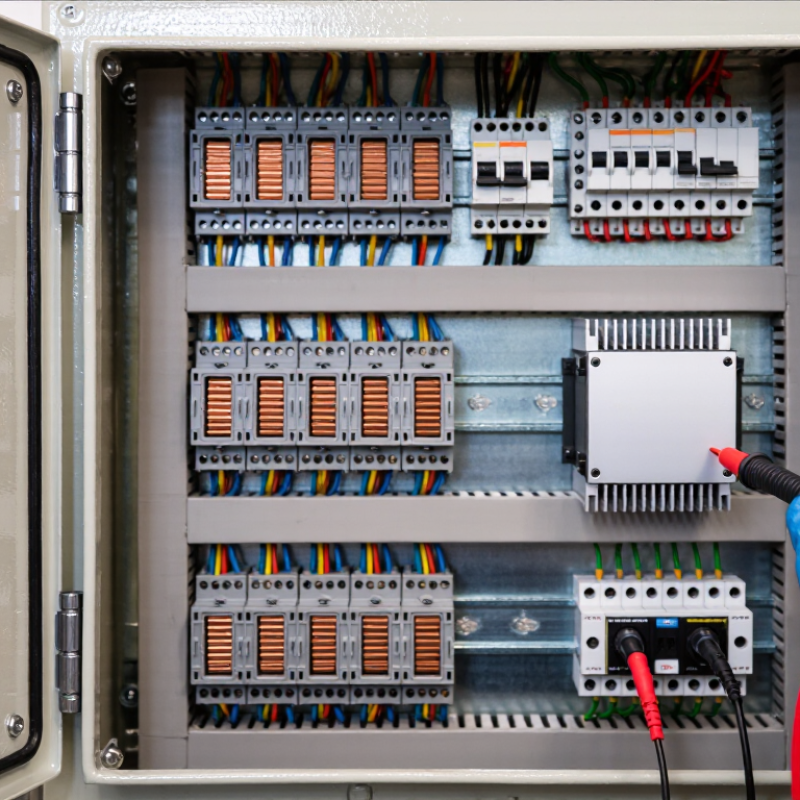
How to Choose the Right Electrical Relays in 2026?
Define the Application and Load Requirements
Start by describing what the relay must switch, where it will operate, and how often it will cycle. A relay controlling a small indicator lamp faces different demands from one switching a motor. Record the load’s voltage, steady-state current, and inrush current. Motors, solenoids, and capacitive loads can draw brief current spikes that exceed normal operating levels. Check whether the load uses AC or DC; contact ratings may differ between them. Also define the control-side coil voltage and available drive current. These details help narrow the options before comparing dimensions or price.
Tips: Note the expected switching frequency, ambient temperature, vibration, and available space. Check whether the circuit needs normally open or normally closed contacts. Leave room for suitable electrical and thermal margin. A paper rating alone may not reflect the real installation.
Think through what should happen if power fails or a contact wears out. For example, a pump control may need a different default state from an alarm circuit. Include enclosure conditions, wiring length, and nearby heat sources in your requirements. Real installations are rarely as tidy as a spreadsheet. A common oversight is sizing only for steady current, then discovering that startup surges shorten contact life. Confirm assumptions against the equipment documentation, and verify the relay under representative operating conditions when practical. If a requirement is uncertain, record it as an uncertainty rather than treating a guess as a specification.
| Application and Load | Typical Load Characteristics | Relay Type to Consider | Key Requirements to Define | Selection Checks |
|---|---|---|---|---|
| Low-level signal switching | Small currents and low-level DC or AC signals; sensitive to contact resistance and electrical noise. | Signal or small electromechanical relay | Signal voltage and current, contact material, number of poles, switching frequency, and isolation needs. | Check minimum as well as maximum switching loads. A relay’s maximum rating does not guarantee reliable operation at very low signal levels. |
| Resistive heating element | Primarily resistive AC or DC load, typically with limited turn-on surge compared with motors or lamps. | Power electromechanical relay; AC solid-state relay may suit frequent switching | Steady-state voltage and current, switching frequency, ambient temperature, and required service life. | Use the rating for the actual AC or DC load. For solid-state relays, account for heat dissipation, leakage current, and any required heat sink. |
| Motor, pump, or compressor | Inductive load with starting current that can be several times the running current; switching can produce electrical arcing. | Motor-rated relay or contactor | Motor type, supply voltage and phase, full-load current, starting method, start frequency, and expected operating cycles. | Choose from the motor or utilization-category rating, not a general resistive-current rating. Check electrical endurance and suppression requirements. |
| LED lighting or other capacitive-input load | May draw a brief, high inrush current when switched on, even when normal operating current is modest. | Inrush-rated power relay, or a suitably rated solid-state switching device | Steady-state current, peak inrush current and duration, number of drivers, switching frequency, and circuit protection. | Confirm the relay’s inrush or lamp-load capability and the manufacturer’s permitted switching conditions. Do not size from steady-state current alone. |
| DC solenoid, valve, or brake coil | Inductive DC load; interruption can create a high-voltage transient across the switching contacts. | DC-rated electromechanical relay or DC solid-state relay | DC voltage and current, coil inductance, release time, switching frequency, and whether fast release is important. | Verify the DC breaking rating. Select a suppression method, such as a diode or TVS device, that suits the required release time and circuit design. |
| Battery-powered or automotive auxiliary circuit | Low-voltage DC load with possible high current, voltage dips, vibration, and temperature variation. | Sealed power relay or contactor rated for the specific DC application | Nominal and maximum system voltage, continuous and inrush current, duty cycle, environmental exposure, and mounting conditions. | Check DC switching and interruption ratings, temperature derating, vibration resistance, terminal capacity, and the required protective-device coordination. |
| Frequent or rapid switching | High operating frequency can increase mechanical wear in contact relays; semiconductor devices may introduce off-state leakage and heat. | Solid-state relay, or an electromechanical relay with a specified high electrical life | Switching frequency, load type, acceptable leakage current, heat-sink space, and required isolation. | Compare electrical life at the actual load, not only mechanical life. For solid-state devices, verify thermal limits and protection against transients. |
| Safety interlock or emergency-stop circuit | Safety-related control function where correct operation and fault response are essential. | Safety relay or safety-rated contactor arrangement appropriate to the system design | Required safety performance level, number of channels, feedback monitoring, reset behavior, and applicable standards. | Use a component and circuit architecture suitable for the required safety function. A general-purpose relay alone does not establish system safety. |
Note: These are application-based selection guidelines, not universal relay ratings. Confirm voltage, current, inrush, load category, ambient-temperature derating, isolation, and endurance against the specific component datasheet and applicable electrical standards.

Whether your solution requires a single pumping application or an expansive engineered system,
CheckPoint is committed to becoming your partner in excellence.