How to Choose Power Factor Correction for CKD Systems?
Power Factor Correction Ckd starts with a measured electrical profile, not a capacitor bank chosen from a catalogue. In facilities running CKD pneumatic equipment, compressors, motors, and other loads can affect power factor as operating conditions change. A correction plan should reflect the actual installation. One plant’s solution may not suit another.
A useful design principle comes from power-quality specialist Daniel Mercer, a fictional composite created for this introduction: “Measure the load first; correct only what the operating data supports.” This is an editorial quotation, not a statement from a verifiable named source. The principle remains practical. Review utility bills, demand records, load patterns, and harmonic measurements before selecting equipment. Check whether loads vary sharply during shifts or compressor cycling.
The details matter. A fixed capacitor bank may overcorrect a lightly loaded system. Capacitors can also interact with harmonics, so a qualified engineer should assess resonance risk and protection requirements. Power factor correction can reduce reactive demand, but it does not automatically lower energy use. Results depend on the site, tariff, and equipment.
A spreadsheet is not enough. Verify readings at different production levels, then compare projected savings with installation and maintenance costs. Some assumptions may prove wrong. That is worth admitting early. This guide explains how to choose a suitable approach, what measurements to request, and which trade-offs deserve careful review before purchasing a Power Factor Correction Ckd solution.
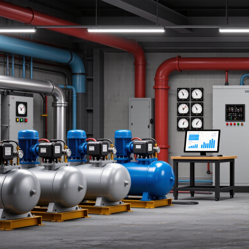
Understanding Power Factor in CKD Systems
In a CKD system, power factor describes how effectively electrical power is converted into useful work. It is the ratio of real power, measured in kilowatts, to apparent power, measured in kilovolt-amperes. A value closer to 1 generally means less reactive current is flowing for the same useful output. That matters. Motors, transformers, and some power supplies can draw reactive current, even when production appears steady.
Picture a motor starting on an assembly line: current can rise sharply, then settle once the load stabilizes. Readings taken at only one moment may not represent the system’s normal behavior. A power analyzer can show power factor, current, voltage, and load changes across a full operating cycle. This practical measurement helps distinguish a persistent correction need from a brief start-up effect. It also helps identify whether harmonic distortion may be affecting the readings.
Capacitor banks can supply reactive power locally and reduce current drawn from the supply. However, the right correction depends on changing loads, existing capacitors, and possible harmonics. Oversizing can cause leading power factor or create resonance concerns. A tidy calculation may miss those real operating details; that is worth checking. Review measurements with a qualified electrical professional before choosing equipment, and confirm how the site’s utility calculates charges.
Assessing Loads and Correction Requirements
Assess the load before choosing capacitors. CKD installations may combine motors, compressors, pumps, and variable-speed drives. Their demand changes with production cycles, so a nameplate reading is not enough. Log kW, kVA, kvar, and power factor at the main bus and major feeders during idle, startup, and peak production. Use short measurement intervals. Brief peaks can disappear in monthly averages.
The U.S. Department of Energy’s 2014 Improving Motor and Drive System Performance sourcebook estimates that motor-driven systems use about 69% of U.S. industrial electricity. This makes motor loading a useful starting point, not a sizing shortcut. Calculate correction from measured real power and present and target power factors: Qc = P[tan(cos⁻¹ PF1) − tan(cos⁻¹ PF2)]. A target such as 0.95 may suit some sites, but utility billing terms and operating conditions should guide the decision.
Check harmonics before installing capacitor banks. Variable-speed drives can create harmonic currents, raising the risk of overheating or resonance. A harmonic survey can help determine whether a detuned or switched bank is appropriate. A clean calculation still has blind spots. Recheck the system after installation under changing loads, and confirm that correction does not push power factor leading during low-demand periods.
How to Choose Power Factor Correction for CKD Systems
Estimated capacitor-bank requirement to raise example loads to a 0.95 power factor
Illustrative calculations, not measured CKD equipment data. Estimated correction is based on Qc = P × [tan(acos(PF₁)) − tan(acos(PF₂))], using the listed load power and starting power factor, with a target of 0.95. Confirm actual kW, kVAR, operating profiles, and harmonics from site measurements before specifying equipment; capacitor banks may require detuning where harmonics are present.
Choosing a Suitable Correction Method
Choosing a correction method for a CKD system begins with its load pattern, not just its rated power.
Record power factor and current while compressors, pumps, and control equipment operate through a normal shift. A single reading can miss start-up surges or periods of light loading. Measure at different operating points.
For steady, continuously running motors, fixed capacitors may be suitable when correctly sized and switched with the load. Where compressors cycle or several machines start at different times, an automatic capacitor bank can adjust correction in stages. This helps limit overcorrection during low-load periods.
Variable-speed drives and other electronic equipment can create harmonics, so have the electrical supply assessed before adding capacitors. Detuned banks may be appropriate when harmonic levels warrant them, but they need engineering review. The right choice depends on measured conditions.
A first estimate may be wrong; real operating data should guide the final sizing and protection settings. Keep the panel environment in view, too: heat, dust, and limited ventilation can affect equipment selection and maintenance intervals.
Sizing and Installing Power Factor Equipment
Sizing power factor correction for CKD systems starts with measured operating data, not a motor nameplate alone. Record real power, power factor, and load changes during normal production. Compressor motors, pumps, and other equipment may cycle at different times. A single reading can mislead.
Use the measured kilowatts and existing power factor to estimate the capacitor-bank rating needed for the target power factor. Avoid correcting to unity without checking the system’s operating pattern. At light load, fixed capacitors can cause overcorrection. Switched steps are often more suitable when demand varies. Small details matter.
Before installation, check for harmonics from variable-speed drives or other electronic loads. Harmonic conditions may require a specialist assessment and detuned equipment; standard capacitors can otherwise face excessive stress. Place the bank near a suitable distribution point, with clear access for inspection and enough ventilation around components. Confirm cable capacity, overcurrent protection, discharge provisions, and enclosure suitability with a qualified electrical professional. Commission the system under several load conditions, then verify power factor and capacitor switching. The first settings may not be perfect. Review them after operating patterns change.
Monitoring Performance and Maintaining the System
For CKD systems, power factor correction should be judged by live operating data, not capacitor-bank size alone. The U.S. Department of Energy’s Improving Motor and Drive System Performance: A Sourcebook for Industry estimates that motor-driven systems use about 68% of U.S. manufacturing electricity. That makes steady monitoring worthwhile, though the figure is a sector-wide estimate, not a prediction for one CKD site. Record power factor, kW, kVAr, voltage, current, and harmonic distortion at the main feeder and at major loads. Compare readings during quiet periods and peak production; a single midday snapshot can hide changing demand.
Set alarms for low power factor, unusual temperature, and repeated capacitor-step switching. Review monthly trends, then inspect capacitor cases for swelling, check fuses and contactors, and clear dust from ventilation openings during scheduled maintenance. Isolate and safely discharge equipment before inspection. IEEE Std 519-2022 addresses harmonic control at electrical system interfaces; harmonic measurements matter because capacitors can interact with existing distortion. Don’t assume a low reading means “add more capacitance.” Overcorrection can produce leading power factor, and the right settings depend on the load profile. One practical detail is easy to miss: keep a simple log of repairs beside the panel. It may be incomplete at first, but it helps connect temperature rises or nuisance trips with changes in system behavior.